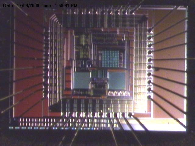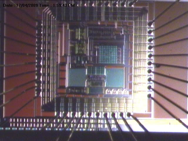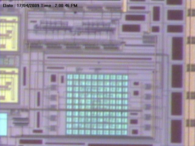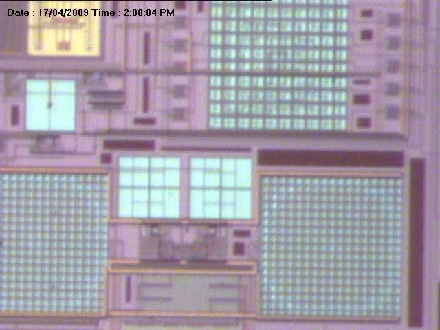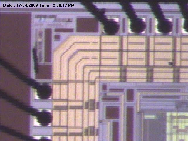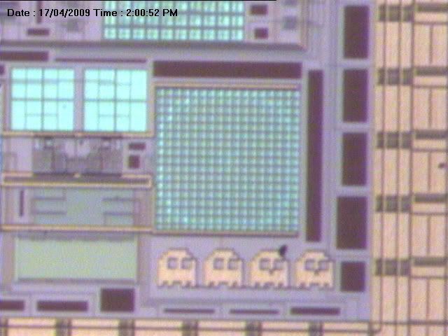
Yay, we just got back our chip, the one we spent one sem to design. So before sending for fabrication, our design was working pretty fine. Now that the real thing is fabricated, will it still work as we intended? That will be the task for us this semester, to perform all kinds of test on the chip to verify our design.

Initial test shows some system working fine. The ADC seems to be ok, but only 1 input tested. LNA seems to have lots of problems. Bandgap is ok. More tests will be perform for the next few weeks and if it works, yay! If not... then pray for at least a b+... lol
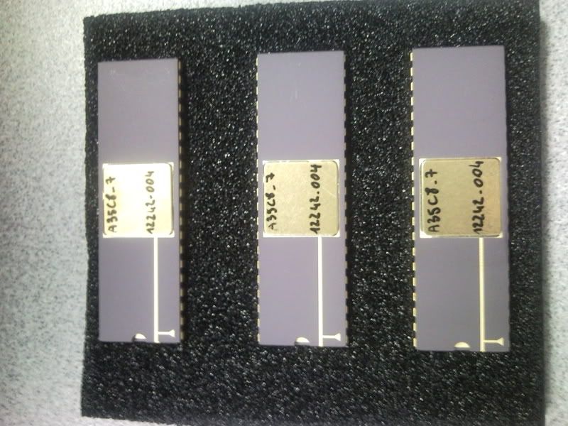
I finally submitted my project for EE3208...took the whole reading week plus last week to rush it out.
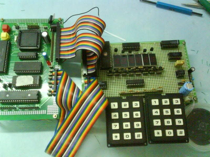
Here's some photos of the final product:
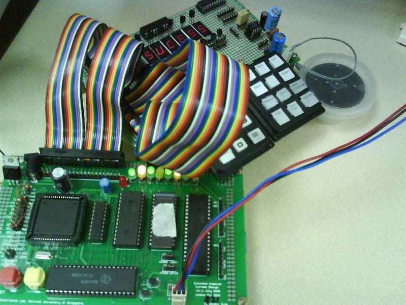
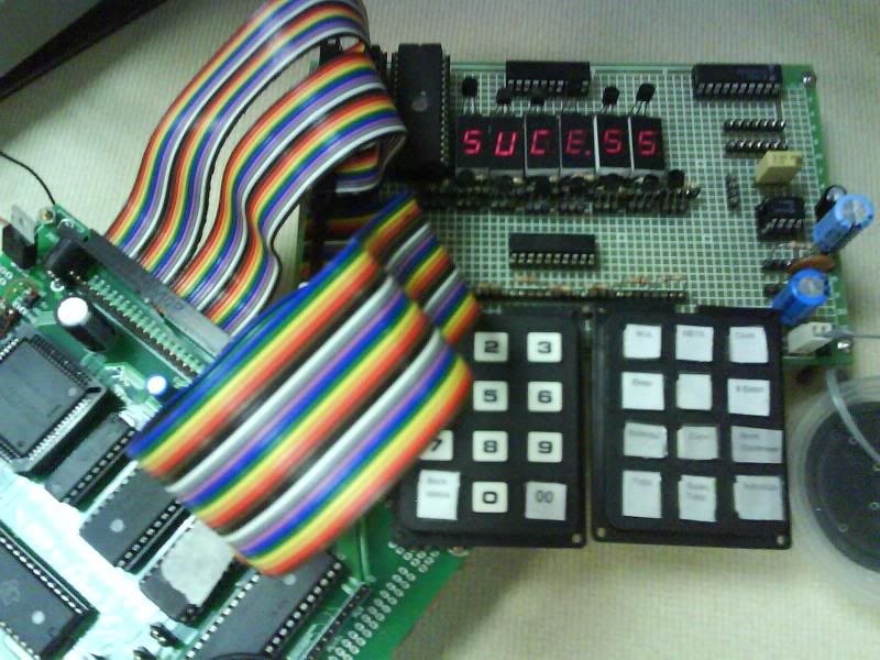
Ah i know success is missing a 'c', but i only limited to 6 characters mah...heh
I always thought software was hard. But i was so wrong as this project has proven to be that software is the easier part as compared to hardware. Why? Cos hardware is sometimes so hard to debug, there can be so many possibilities and uncertainties.
Ah, whatever, i still have 2 more papers to go.. and most people have already finished their exams liaoz. Sian..back to mugging.
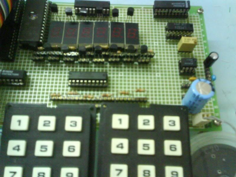
Finally finally!! After 2 days of debugging and stressing my ass off, my keypad and 7 segment finally work! Ahh this is for yet another project module, EE3208. Deadline for this project is 7th may wor...
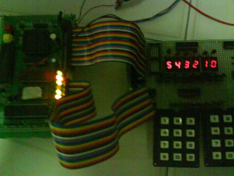
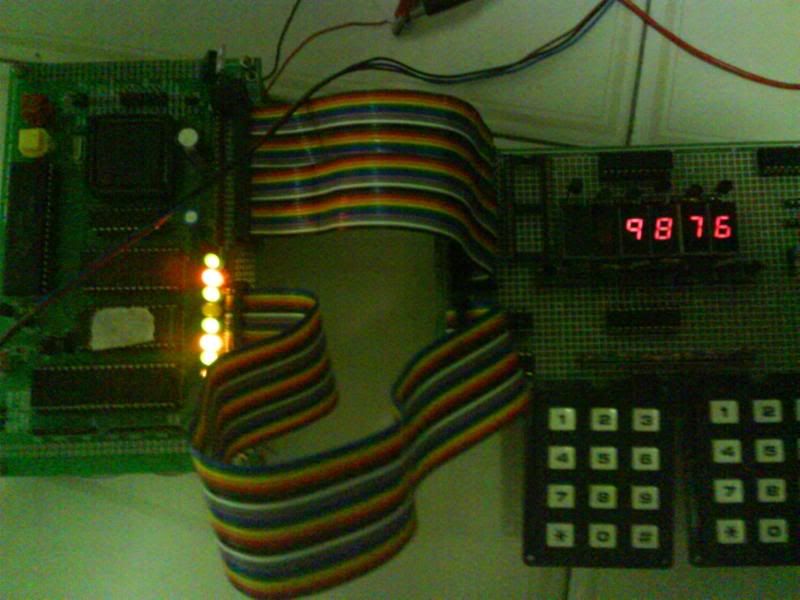
Just moments ago, i finally found the error in my codes that made my 7 segment went berserk earlier in the lab. Here, my system display 543210 and then switch to 9876 after 1 second and 543210 again and so on. This is just a test program to test the 7 segment.
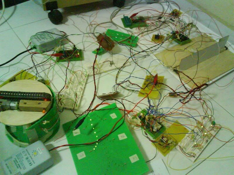
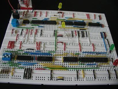
More photos, taken after i wire wrap. Yes wire wrap, bloody hell, you've gotta marvel at the wonderful invention of wire wrapping, making you connect wires for more than TEN TIMES longer than you otherwise would if using breadboard instead and poking wires into those lovely holes. Now, this damn stupid thing cause me like weeks to connect just a simple system...
Now, i better go try to make the sound part work, if not i am still quite screwed. There's a reason why the project is called "Talking cash register"..
Finally, after 1 semester of hard work, pulling of hair wires, soldering accidents extension of wires, late nights and stressing over whether we have enough features, the 6 MCs project module came to an end after a rather good presentation last Friday.
Our team had lots of fun in this project. Its always great to see our concepts and design materialize into the real working product. And we also put in alot of effort in making the model looks professional, and it all pays off because in the end it really looks very good and impressive, and the sense of achievement is just beyond words can describe. We also put in alot of effort on the GUI and SMS, learning much more things than required, to present our project in the best way possible.
In all, it was a great project and no matter what kind of grades we get, we can proudly say we did our very best!
Now, let the photos do the talking.
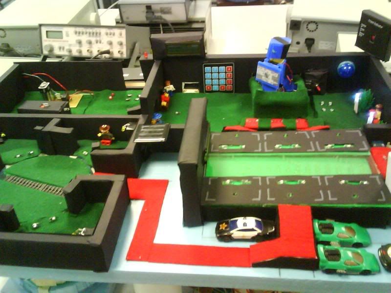
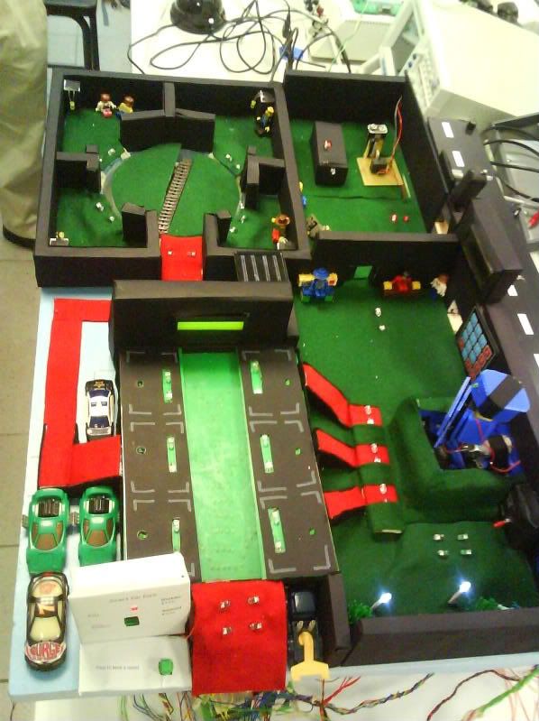
EE2001, The Airport of the Future, presented by group 4-03:
The Graphical User Interface (GUI):
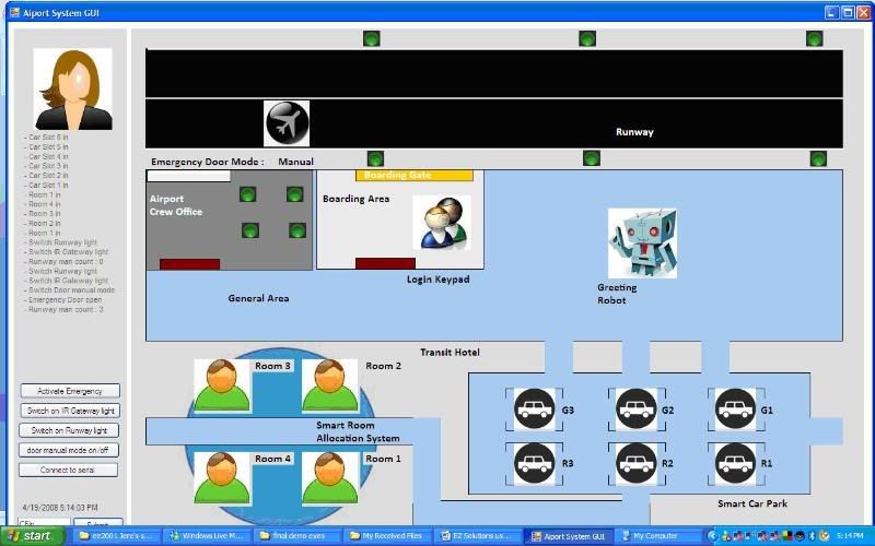
The GUI has an overview of our entire airport and can control certain features as well as performing real time updating of the status of the transit rooms allocation as well as the smart car park. One of our best features in this project.
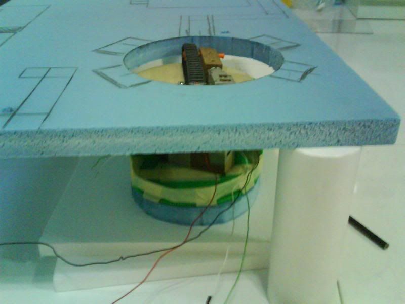
The smart transit rooms allocation system:
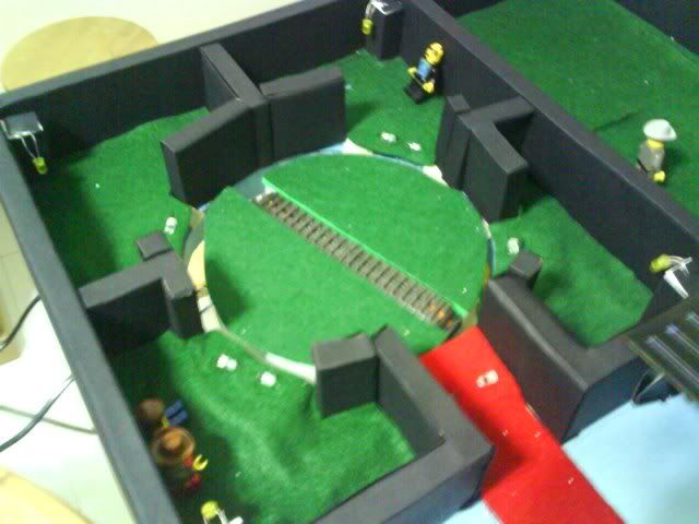
This one got a rotating platform plus a travellator on top. It basically allocate traveler to the nearest available transit room. Spent a great deal of time to make this feature as perfect as possible.
The smart car park:
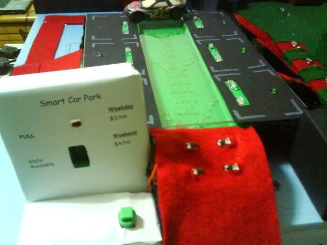
The car park provides guiding light for drivers to the nearest available slot. It also have a room booking system and the driver will be directed to the slot nearer to the transit rooms.
The smart queuing system and the SMS system:
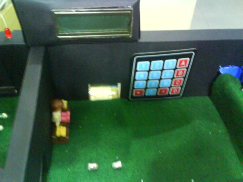
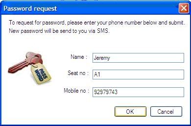
Smart queuing system requires traveler to login into the system by first obtaining a one time password from the SMS system and then entering into the keypad in the waiting area. The system then prompt travelers to board plane row by row based on their seat numbers and whether that passenger to the particular seat has login.
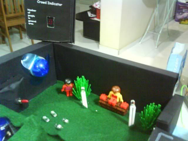
The greeting robot and interactive directory:
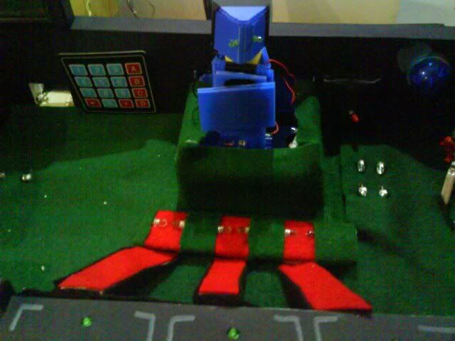
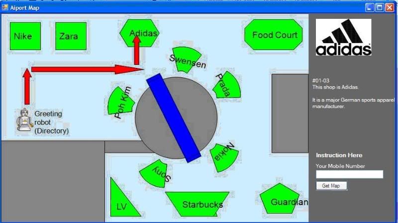
Next comes the greeting robot which turns to face the travelers as they come out of the car park. On it is the interactive directory where travelers can check out what shops are there in the shopping area as well as the route to take to get there. Moreover, they can have the map sms to their handphone!
The Lounge power management system:
Solar panel for the lounge:
Smart energy control allows the fan to blow at speed corresponding to the number of people in the lounge. Also lighting depends on the amount of sunlight on the solar panel.
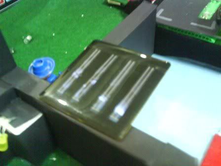
More photos of us at work:
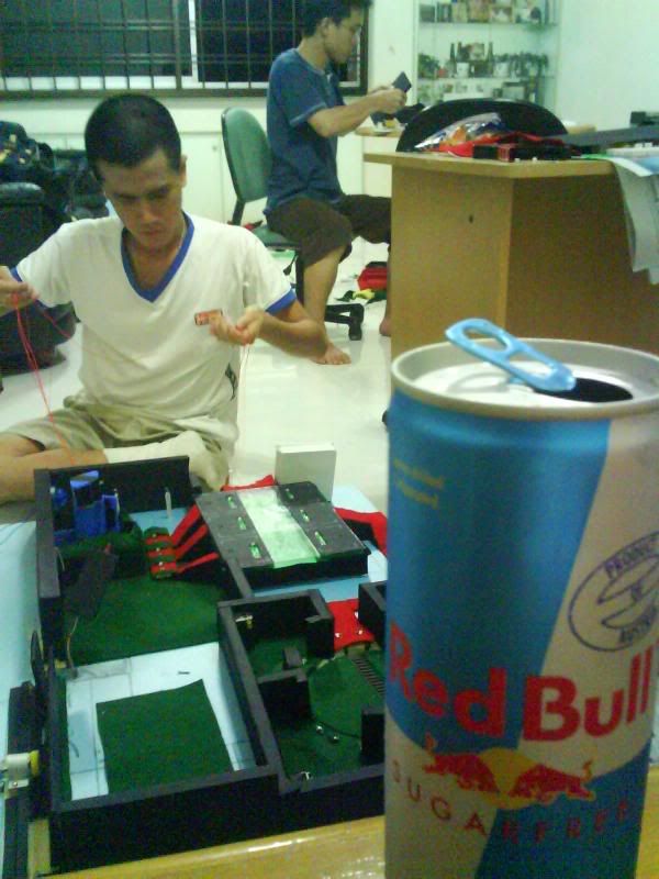
Red bull kept us awake all night through! (Eh actually only I drank...together with coffee and had a terrible stomachache the next day..jeez )

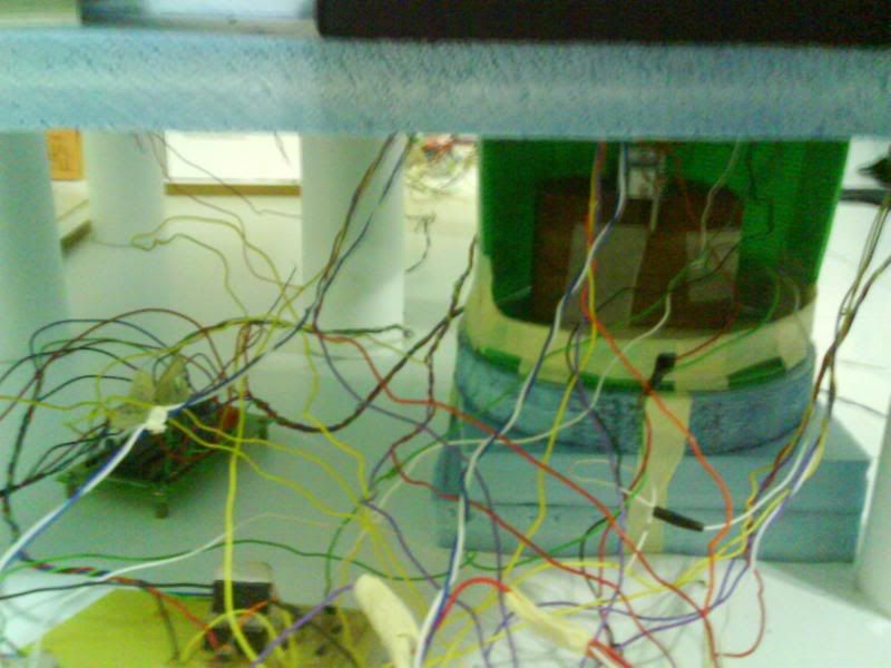
Messy wiring below....
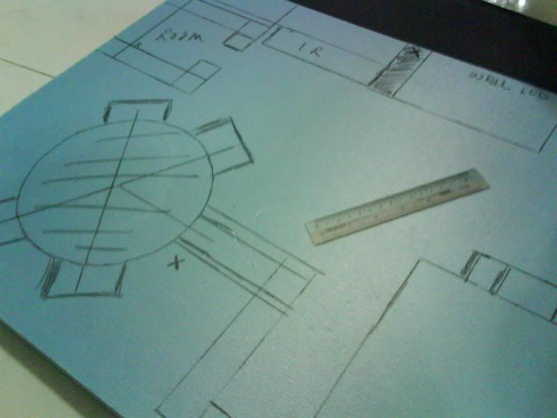
Planning stage for the model:
Taking measurements:
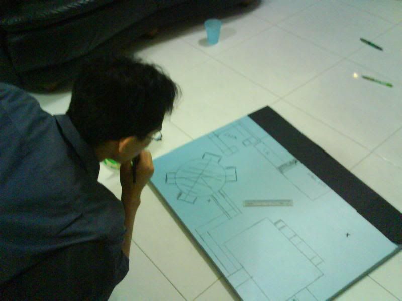
The designer at work:
More messy wirings during testing phase:
Once again, this is The Airport of the Future!
Of course, a great project should end with a celebration of sorts. Right after the presentation, we treated ourselves to a sumptuous meal at Sakura!


Okay no more photos after this, too busy eating..lol.
GG!
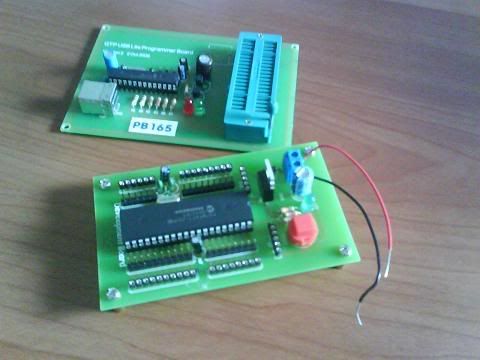 This is the PIC development board which contains the PIC16F877, a 40 pins PIC microcontroller, and other components.
Took us like almost 3 hrs to solder, program and test it. This one is for our EE2001 fam lab, and which will be used for our final product as well, the "Airport of the future".
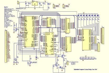
Now now, the above is considered ok one. Imagine the horror when i saw the schematic for our EE3208 part1 project (below). I almost pee in my pants. Sheesh..
 When studying for exams, there will be a point where your brain voltage increases until the voltage drop across the oxide at the
 drain brain edge equals that of the terminal voltage. This is when your brain goes into saturation mode and whatever increase in input doesn't affect the output anymore.
This is detrimental to the exam preparation as it might result in the loss of the electrons to useless stuff like msn, tv, games and blogging.
But fear not! Your brain channel length is not always a constant as what the ideal brain current-voltage relationship have assumed. Thus, due to the effects of channel length modulation, your brain current still can increase a little bit even after saturation.
But the marginal gain from saturation of the brain is very very little, so its better to let the electrons wander off and let the brain voltage drops till the linear region. It's in the linear region that your brain voltage will increase linearly with your input and thus making your learning, studying, mugging more effective.
Dun mug too hard guys, take a break once in a while and blog crappy stuff like this! Ha. =)
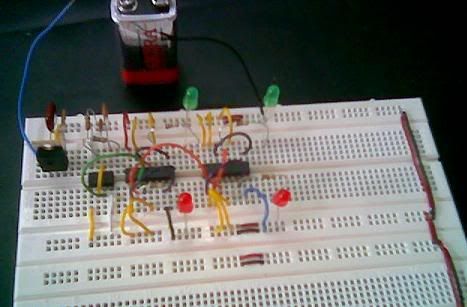
 It's done, my tsunami alert system for my EE2006 project. After wiring according to my breadboard planning, the design finally materialized into the real product and most importantly, it works!! Sweet. Well, of course that's after doing some testing and debugging and re-wiring for a small part of the breadboard due to some errors in my breadboard planning. Alright, now that this one is done, I can divert my attention to other stuff like prep for EE2009 e-test and EE2006 VHDL test, genes and society essay, catching up and doing tutorials..
Some tips for debugging:
- First, check that the Vcc is connected to 5V and ground grounded for all chips.
- Then, check that all input pins of all the chips are connected. If it's not connected to any other chips, it should be either grounded or 5V-ed so that it wouldn't pick up any stray signal and screws up your circuit.
- Use LEDs to confirm that the intermediate signals are as what you expected or to check if the components are working well. Example: I used yellow LEDs (see above pic) to check that my 555 timer and the single pulse are indeed working the way I want them to.
- If something is not right, trace the wires and run the logic in your mind to see if the connection is correct.
- If all is connected the way it should be, then try replacing the chips involved; they might be faulty..
- If all else fails, go back to your xilinx software and run the simulation again to verify. If you happens to discover something that undermines the correct functioning of the circuit at this point in time, I would say that you are quite screwed.
Was trying to wire up my tsunami alert system for my D1 project for EE2006, but realized it's almost impossible to do it without planning the breadboard. So a quick search in the net landed me on this breadboard simulator. However, after trying it out for a while, i realized the simulator's breadboard is slightly smaller than our breadboard. Hence, i decided not to use it.
So I tried drawing it out on a graph paper. It was also a futile attempt as I got frustrated when i had to correct a mistake and had to rub the lines out and made a mess out of it.
 Then, I thought of using excel. By making use of the cells, I divided the excel worksheet into the required number of "holes" in the breadboard, representing each in one box and coloring them in light green. White portions then represented the empty spaces within the breadboard. Vcc is coded red, ground is black and clock pulse is pink. The chips are colored dark grey and other components like the resistors and capacitors are given light grey. The rest of the colors represent the rest of the wires to interconnect the different input/output of the chips. Cells for a single wire are then merged up to ensure that overlapping of wires are disallowed.
So yup, with all the rules I set for my breadboard planner, I went ahead to plan my breadboard. And surprise surprise, I managed to do it!! Woah, I was quite amazed with myself when I finally somehow managed to plan it out nicely. Heh.
Now its time for the most difficult part: the real wiring.
 I am supposed to design a tsunami alert system for my D1 project for EE2006. Basically, if the seismic activity (S_amp: on a scale of 0 to 5, where 5 is the highest activity) is greater than 3, raise the alarm by flashing a red light for S_amp*3 time unit and follow by (16 - S_amp*3) time unit of green light. If S_amp is 3 or less, leave the system at 16 time units of green light.
Design of the circuit is due next Wednesday, but I have yet to come up with anything due to the mid term tests. I am so screwed. =(
Was playing with the breadboard and then I itchy finger go and cut the legs of the 10 nano capacitor so as to fulfill the requirement set out for us: "5) The legs of the resistors, capacitors and LEDs should be only long enough to connect any two points on the breadboard." Cut cut nevermind, but I cut too SHORT.... Then i go bend the legs in hope that it still can fit into the 2 connecting points of the breadboard. Bend bend bend, then it BROKE. Holy shit, I am so screwed. So sian lar, cannot play with the breadboard liao. =(
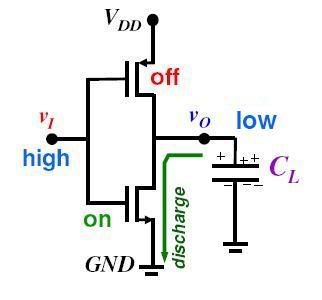 (For those who are not familiar, the picture to the left is a CMOS inverter and is equivalent to a NOT gate. Basically, it inverts the input signal.)
Nus exams are like CMOS inverters. Go in with high confidence, but during the operation discharged all my charges and pull my confidence signal down to ground. So end result is a low confidence level for the output.
Perhaps next time should try to go in with low confidence. Then I will be charged up and subsequently can pull my confidence signal up to Vdd. Then got high output. Perhaps my switching speed from low to high wasn't fast enough. Maybe i should have increased my width (W) and reduced my length (L), since t(PLH) is inversely proportional to (W/L). Ok I am losing it...
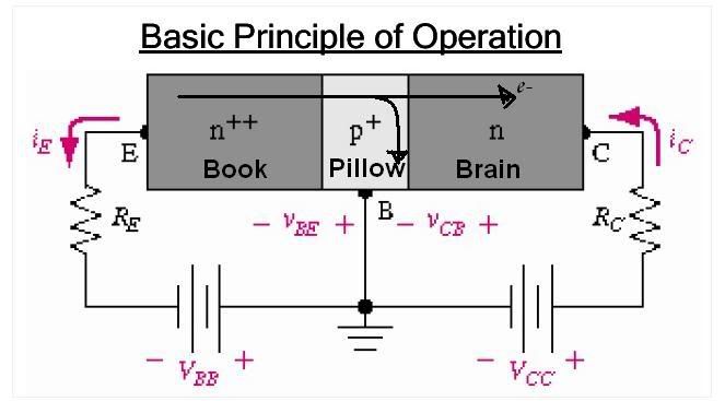
The best way to absorb knowledge is to put your book below your pillow when you go to bed. The book is very heavily doped with electrons knowledge compared to that in your brain. Thus, the knowledge in your brain is referred to as the minority carriers. Due to this diffusion gradient of the knowledge concentration, there will be a minority carrier injection from the book into the brain. However, precaution must be made to ensure that extraction of the minority carrier from the brain will not occur. So there must be a forward biasing and not a reverse biasing for this reason. Hence, one must be highly motivated when trying this out; else the experiment will fail with detrimental results.
Furthermore, we want as much knowledge as possible to reach the collector brain from the emitter book without recombining with the majority carrier (air) in the base pillow. For this reason, the width of your pillow needs to be small enough. So go get a thinner pillow before doing this for maximum performance.
Hope you will still appreciate the BJT (Book-Brain Judgmental Transfer), although its now not highly regarded in the market anymore due of the advent of the MOS-FET (Method Of Studying via Fundamental Education Transfer).
Crap, this is all Jhalley's fault, he started it! See.. this is what engin students crapped about during their breaks..
Similar crap: Cheese Sausage Semiconductor
Next time when you play with an electronic gadget, be sure to offer your solemn respect to the billions and billions of brain cells that sacrifice each day in electrical engineering undergrads in an effort to perform the circuit analysis for their electronics class.
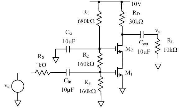
Things are getting more complicated as more than one transistor were brought into the picture and what seems to be the easiest module before the break, now ensues much uncertainties in the minds of many. Lecturer said perhaps we are just not used to it, but with more practices and time, the analysis of multistage transistors will be like differentiation to us. I certainly hope so. Yet, there isn’t much time left. Tick tock.
 Poor cheese sausage was being modeled as a semiconductor by 3 crazy (or more appropriately termed as the "yeow syndrome") engineers this afternoon over lunch at business canteen.
The sausage comprises of meat atoms positioned regularly in the sausage lattice. There are small amount of point defects which causes some ugly hollows in the sausage. Some grain boundaries, which are generally undesirable, are present, causing significant amount of scattering of the cheese particle, which is modeled as the negatively charge carriers aka the electrons. Photogeneration in the form or light or heat excited the electrons cheese, causing them to spread outwards towards the vacuum level, while creating a cheese-hole pair in the process. It was rumored that the sausage was doped, perhaps with a group 5 elements including the likes of oil and chilly sauce, in an effort to enhance the electrons cheese concentration (n-type sausage!) and thus the sausage electrical cheesy properties.
Someone gotta stop these 3 lunatics before they start creating a Gaussian surface around the cheese sausage and taking the surface integral to find the electric cheese field density…