(Via DK)
 You are totally sick of your life in the office and decided to kill yourself. However, you got only 5 mins to do so, else you need to drag yourself to yet another meeting.
I did it in 1 mins 39 sec, how about you?
Kill yourself here.
 The reason why life sucks is because the world sucks.
But if the world doesn't sucks, we wouldn't be sticking onto the ground.

"Things you want, you cannot get.
Things you can get, you may not want."
-- EE2009 Lecturer on Spectrum Estimation.
Well, that's life.
(Via Jere's)
From life to death there are five stages
denial
anger
bargaining
depression
acceptance
Its not that death is hard, its the transition we fear.
Its the same for everything that goes wrong.
There's a time for everything. Maybe its time for acceptance.
Guess life is not a smooth road and failures inevitably will come our way sometimes. Learning from it and pulling yourself out of depression and thereby accepting it, will then help you overcome it.
Maybe its time for acceptance.
 (Via Fabian's)
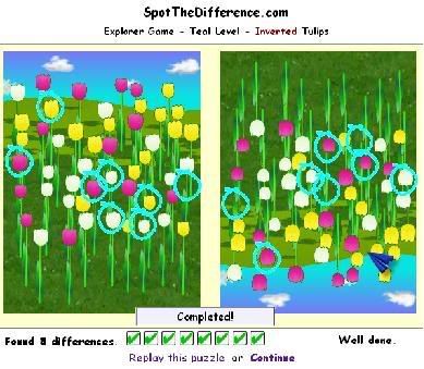
Try this out, spot the difference game, very much like the photo hunt game in the arcade. This one, however, have a lot of other add ons, such as moving image, mirror image, and inverted image (omg this one sucks).
Each level have a few puzzles to solve and a new level will be unlocked if you clear all the puzzles in the current level. I am now at Teal level, where they first introduced the inverted image mode. I was so lousy at this mode that the above puzzle took me damn long and I had to cheat in order to find the last one.. well, i copied the image into paint and invert the image back again to find the last one...lol!
Ohh and there's the option of using "magic spot" to auto-spot the difference for you, but that one is limited as you only get one "magic spot" when you unlock a level.
Check it out here: Spot the difference!
(Via LancerLord)

Design your own paper planes and see how well they fly!
I think I sux in this; the best I can manage is only 47.7m, can you beat that?
Try it here: Paper Pilot
 I was excited and motivated for a while; I thought there was hope. Yet, that was just self-delusion I soon realized. And when reality knocks back, I realized how far I am from my goal and a sense of disappointment, sadness and then regret coursed into me. Hope is such a double edged sword. Sometimes, I rather not have any hope at all, for it has always caused me more harm than good. Yet, I still grip on tightly onto my hopes, hoping what I hope for do really come true one day, for that’s the only driving force that kept me going.
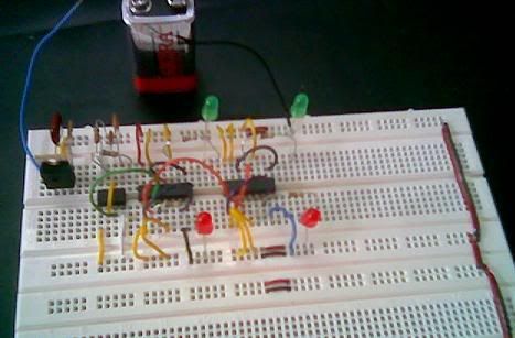
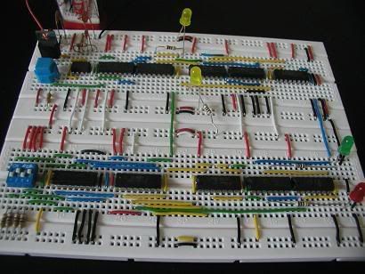 It's done, my tsunami alert system for my EE2006 project. After wiring according to my breadboard planning, the design finally materialized into the real product and most importantly, it works!! Sweet. Well, of course that's after doing some testing and debugging and re-wiring for a small part of the breadboard due to some errors in my breadboard planning. Alright, now that this one is done, I can divert my attention to other stuff like prep for EE2009 e-test and EE2006 VHDL test, genes and society essay, catching up and doing tutorials..
Some tips for debugging:
- First, check that the Vcc is connected to 5V and ground grounded for all chips.
- Then, check that all input pins of all the chips are connected. If it's not connected to any other chips, it should be either grounded or 5V-ed so that it wouldn't pick up any stray signal and screws up your circuit.
- Use LEDs to confirm that the intermediate signals are as what you expected or to check if the components are working well. Example: I used yellow LEDs (see above pic) to check that my 555 timer and the single pulse are indeed working the way I want them to.
- If something is not right, trace the wires and run the logic in your mind to see if the connection is correct.
- If all is connected the way it should be, then try replacing the chips involved; they might be faulty..
- If all else fails, go back to your xilinx software and run the simulation again to verify. If you happens to discover something that undermines the correct functioning of the circuit at this point in time, I would say that you are quite screwed.
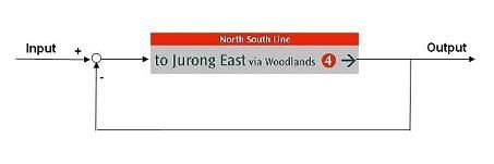 I think I must relax abit on those tutorials, especially system and control. While having a conversation with my friends today before tutorial, I actually said "output" of the train when I meant "doors" of the train. Sheesh..
Was trying to wire up my tsunami alert system for my D1 project for EE2006, but realized it's almost impossible to do it without planning the breadboard. So a quick search in the net landed me on this breadboard simulator. However, after trying it out for a while, i realized the simulator's breadboard is slightly smaller than our breadboard. Hence, i decided not to use it.
So I tried drawing it out on a graph paper. It was also a futile attempt as I got frustrated when i had to correct a mistake and had to rub the lines out and made a mess out of it.
 Then, I thought of using excel. By making use of the cells, I divided the excel worksheet into the required number of "holes" in the breadboard, representing each in one box and coloring them in light green. White portions then represented the empty spaces within the breadboard. Vcc is coded red, ground is black and clock pulse is pink. The chips are colored dark grey and other components like the resistors and capacitors are given light grey. The rest of the colors represent the rest of the wires to interconnect the different input/output of the chips. Cells for a single wire are then merged up to ensure that overlapping of wires are disallowed.
So yup, with all the rules I set for my breadboard planner, I went ahead to plan my breadboard. And surprise surprise, I managed to do it!! Woah, I was quite amazed with myself when I finally somehow managed to plan it out nicely. Heh.
Now its time for the most difficult part: the real wiring.
 I am supposed to design a tsunami alert system for my D1 project for EE2006. Basically, if the seismic activity (S_amp: on a scale of 0 to 5, where 5 is the highest activity) is greater than 3, raise the alarm by flashing a red light for S_amp*3 time unit and follow by (16 - S_amp*3) time unit of green light. If S_amp is 3 or less, leave the system at 16 time units of green light.
Design of the circuit is due next Wednesday, but I have yet to come up with anything due to the mid term tests. I am so screwed. =(
Was playing with the breadboard and then I itchy finger go and cut the legs of the 10 nano capacitor so as to fulfill the requirement set out for us: "5) The legs of the resistors, capacitors and LEDs should be only long enough to connect any two points on the breadboard." Cut cut nevermind, but I cut too SHORT.... Then i go bend the legs in hope that it still can fit into the 2 connecting points of the breadboard. Bend bend bend, then it BROKE. Holy shit, I am so screwed. So sian lar, cannot play with the breadboard liao. =(

Base jumping 2: Survive the jump and dun be the last! Quite addictive!
 I discovered this sweet extension for firefox a few days back. Tab group extension allows you to group your tabs. Well, it appears to be nothing fascinating, but for someone who surf with over 10 tabs, it's really cool. I always envision the time where I could organize my tabs into groups so that I easily identify the tabs I desired. Now I have it!
"The greatest regret in my life is to be good in numbers instead of words.
If I were to be good in words, I would have gone to Arts fac.
But if I have to be good in numbers, then I must be so good with them that I do not have to suffer this much in engineering."
--- A fellow engineering student during the mid term test period.
Currytan just returned from a 3 days mission: Operation fast and furious, which consists of 1 dawn and 3 evening attacks.
Heavy casualty was initially expected for the first insertion, EE2012, but somehow the enemy was not as strong as predicted. Casualty rate for the first mission was thus kept to a minimum as a result.
The second attack, EE2006, was an easier mission, although there was some ambiguity over whether zero is divisible by 4. But if zero were to be divisible by 4, then the design will be too easy. So I decided to, taking the viewpoint of the lecturer, make my life difficult by defining zero to be not divisible by 4 and designed a more complex circuit.
I was somewhat disappointed with my performance of the next mission, EE2010. Terror overwhelmed me as I read the first 2 questions, but it turns out that those were not as hard as it seems. I panicked for the first due to the 2 sources in the RLC circuit. But I realized the transfer function could still be derived by considering KVL and KCL and assuming initial parameters carefully. Or just use superposition lar (why din I think of that? Sheesh...). As for the second question, the word convolution shocked me. Serious, my jaws literally dropped when I saw that. I know what convolution is and how to do convolution, but hell, how to relate that with transfer function was a mystery. Yet, I realized the question only required us to replace the convolution expression with the transfer function, very much like substitution of constants into an equation and find the result. I managed to realize the above 2 mistake only at the last 10 mins. So to say the least, I rushed and panicked (again) and probably made some careless mistakes.
The last one, GEK1527, was quite alright, although a few guesses was made along the way.